Publicerad den Lämna en kommentar

Ukraine hackers target GLONASS for cyberattacks

Photo: EvgeniyShkolenko/iStock/Getty Images Plus/Getty Images

Photo: EvgeniyShkolenko/iStock/Getty Images Plus/Getty Images

Ukraine’s hacker underground named GLONASS as one of its top priorities, according to media reports that cite a post on the “IT army” Telegram channel.

The IT army, formed on Saturday, is a collective of volunteer hackers. “We need to mobilize and intensify our efforts as much as possible,” the IT army posted.

Besides GLONASS, hackers are focusing on Russian telecom companies and the railway network in Belarus — a key staging area for Russia’s invasion of Ukraine.

The Belarusian Cyber Partisans, a hacking team focused on Belarus, told Reuters it had disabled railway traffic systems in Belarus. Another target is the electrical grid.

Publicerad den Lämna en kommentar

France develops GNSS backup service using nanosatellite

Image: Rick_Jo/iStock/Getty Images Plus/Getty Images

Image: Rick_Jo/iStock/Getty Images Plus/Getty Images

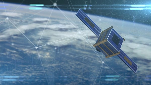
France has begun the Synchrocube project with an aim to provide a complementary service to GNSS. In the project, a low-Earth-orbit nanosatellite will provide synchronization functions when GNSS navigation signals are unusable.

Development of the Synchrocube is part of the French recovery plan for the space sector. Planned to be 6U in size (typically 20 × 10  × 34.05 cm),  the satellite platform is being developed by Syrlinks, which will provide both the payload and the ground receiver necessary to provide the location and timing service.

Consortium

Besides Syrlinks, companies taking part in the Synchrocube project include U-Space, (nanosatellite platform supplier), Anywaves (miniature antennas for satellites constellations) and Comat (satellite instruments).

By pooling their technologies, the companies in this consortium demonstrate their ability to provide effective and competitive solutions to respond to ambitious space programs.

“Synchrocube represents a major evolution for Syrlinks,” said Guy Richard, Syrlinks CEO. “The implementation of a project as sizeable as this opens up new commercial prospects for the company. Syrlinks, initially known as a satellite subsystem manufacturer, is on its way to becoming a service provider.”

Publicerad den Lämna en kommentar

FGI-GSRx software-defined GNSS receiver goes open source

NLS-FGI logo

The open-source release of FGI-GSRx software receiver widens its user base and offers researchers, students and developers a chance to utilize the research platform for new innovations.

The GSRx software receiver, developed by the Finnish Geospatial Research Institute (FGI), is now being released as open source for use by the GNSS community.

FGI-GSRx has been extensively used as a research platform for the last decade in different national and international research projects to develop, test and validate novel receiver processing algorithms for robust, resilient and precise positioning, navigation and timing (PNT).

FGI-GSRx has been used to develop algorithms for detecting GNSS jamming and spoofing events in several past R&D projects. It is also used to develop mitigation algorithms to offer a resilient PNT solution to the user.

The FGI-GSRx software receiver will be discussed in the next edition of the textbook GNSS Software Receivers by Borre, Fernández-Hernández, Lopez-Salcedo and Bhuiyan. The book will be published by Cambridge University Press in August.

Uses of the software receiver

The software receiver can be used in universities and other research institutes to provide graduate-level students and early-stage researchers with hands-on training in GNSS receiver development. It can also be used in the GNSS industry as a benchmark software-defined receiver implementation.

The software receiver is already being used in the “GNSS Technologies” course offered widely in Finland at the University of Vaasa, Tampere University, Aalto University and the Finnish Institute of Technology.

The open-source release of FGI-GSRx will enable any third-party developer, researcher or student to use the platform to develop, test and validate innovative algorithms. It offers a flexible interface and configuration files, so that researchers can further implement their own codes or algorithms at different receiver processing stages. This allows the user to go much deeper into the coding without addressing all the implementation details, explained Research Professor Zahidul Bhuiyan, FGI, National Land Survey of Finland.

Meeting evolving industry needs

The GNSS market has faced a transformation in the past two decades, with new features and signal properties being added to the modernized satellite navigation systems at an increasing pace. A software-defined receiver enables algorithm optimization and testing in this rapidly changing industry.

The multi-constellation FGI-GSRx receiver has evolved to provide diversity and improved accuracy. When the FGI-GSRx was first developed, it was able to track the Galileo test satellites GIOVE A and GIOVE B. Since then, FGI researchers have been continuously developing new capabilities to the software receiver with the inclusion of Galileo in 2013, the Chinese satellite navigation system BeiDou in early 2014, the Indian regional satellite navigation System NavIC in late 2014, and the Russian satellite navigation system GLONASS in 2015.

Publicerad den Lämna en kommentar

Advanced Navigation launches Boreas digital FOG

Photo: Advanced Navigation

Photo: Advanced Navigation

Advanced Navigation has launched a new fiber-optic gyroscope inertial navigation system (INS), named Boreas. It is an ultra-high accuracy, strategic-grade INS, offering a reduction in size, weight, power and cost. Boreas is the first product to be released based on Advanced Navigation’s new DFOG (digital fiber-optic gyroscope) technology, which is the culmination of 25 years of development involving two research institutions.

The Boreas is targeted at applications requiring always-available, ultra-high accuracy orientation and navigation including marine, surveying, subsea, aerospace, robotics and space.

“Boreas is the first product on the market to offer our patent-pending DFOG technology,” said Advanced Navigation CEO Xavier Orr. “DFOG represents a step-change for fiber-optic gyroscopes. With Boreas’ ultra-high-accuracy and strategic-grade performance combined with the reduction of size, weight, power and cost by 40%, we will be able to enable new industries and applications that were never possible before.”

The Boreas delivers strategic-grade bias stability of 0.001 deg/hr. This allows it to achieve ultra-high roll/pitch accuracy of 0.005 degrees and heading accuracy of 0.006 degrees. Boreas allows for full independence from GPS with dead-reckoning accuracy of 0.01% distance traveled with an odometer or Doppler velocity log.

The Boreas features ultra-fast gyro compassing, taking only 2 minutes to acquire heading in both stationary environments or on the move. Gyro compassing allows the system to determine a highly accurate heading of 0.01 degrees secant latitude without relying on magnetic heading or GPS.

The Boreas contains Advanced Navigation’s sensor-fusion algorithm, which is more intelligent than the typical extended Kalman filter. The algorithm is able to extract significantly more information from the data by making use of human-inspired artificial intelligence. It was designed for control applications, with a high level of health monitoring and instability prevention to ensure stable and reliable data.

Advanced Navigation designed Boreas from the ground up for reliability and availability. Both the hardware and software are designed and tested to safety standards, and it has been environmentally tested to mil standards.

The system is designed for a mean time between failures of 500,000 hours. Additional features include Ethernet, CAN and NMEA protocols, as well as a disciplined timing server providing PTP. An embedded web interface provides full access to all of the device’s internal functions and data. Internal storage allows for up to one year of data logging.

Publicerad den Lämna en kommentar

OxTS releases Georeferencer 2.0 with lidar data

Screenshot: OxTS

Screenshot: OxTS

OxTS Georeferencer 2.0 is now available, introducing several key improvements, particularly for professional lidar surveyors.

Version 1, introduced almost two years ago, has since been upgraded with integration of 30 new lidar sensors, as well as providing multiple user-experience enhancements.

Surveyors can use Georeferenceer alongside any OxTS inertial navigation system (INS) to quickly and easily georeference lidar data from multiple sensors to create precise 3D point clouds.

Version 2.0 highlights

Global coordinates. OxTS Georeferencer 2.0 users can now process data in a range of coordinate systems. These include local coordinates, ECEF and LLA (latitude, longitude and altitude).

New processing options. Users can maximize the usability of their point clouds and minimize data size through a range of processing options, including:

  • filter points by position uncertainty keeping every point within a specified accuracy
  • maximize the accuracy of the data while minimizing data size with a Voxel sampling algorithm
  • filter points by intensity, azimuth and elevation angle of the lidar
  • ilter points by speed and range from a vehicle.

Improvements in map file creation. OxTS Georeferencer 2.0 can add the direction from which each point is surveyed into the point cloud, allowing mesh surfaces to be easily reconstructed.

Furthermore, OxTS Georeferencer 2.0 gives surveyors the ability to add point-normal information into the point cloud and view the vehicle trajectory as a point cloud.

Processing advances. Users benefit from better performance due to revisions of the OxTS Georeferencer processing algorithms. With version 2.0, users can process point clouds faster than before and take advantage of improved precision and consistency of the boresight calibration feature, which now utilizes target dimensions.

Publicerad den Lämna en kommentar

DroneShield and Teledyne FLIR join on drone detection

DroneShield Limited and Teledyne FLIR are collaborating on a joint sensing and mitigation solution for unmanned aerial threats.

Teledyne FLIR is extending its counter-UAS thermal-imaging sensing technology to the DroneShield platform, which has developed and applied its artificial intelligence and machine-learning software algorithms via radiofrequency (RF) sensing and computer vision technologies.

The addition of Teledyne FLIR thermal camera hardware and expertise will enable military customers to improve detection, including identifying and tracking numerous unmanned threats in the thermal and RF spectrums at considerable range, providing the capability within a single system.

A major Western military agency will be deploying the combined system at one of the best-known military testing ranges in the world.

The DroneShield DroneSentry-C2 command-and-control system with Teledyne FLIR thermal imaging sensing technology. (Screenshot: DroneShield)

The DroneShield DroneSentry-C2 command-and-control system with Teledyne FLIR thermal imaging sensing technology. (Screenshot: DroneShield)

Publicerad den Lämna en kommentar

EU requires Galileo for smartphone emergency calls

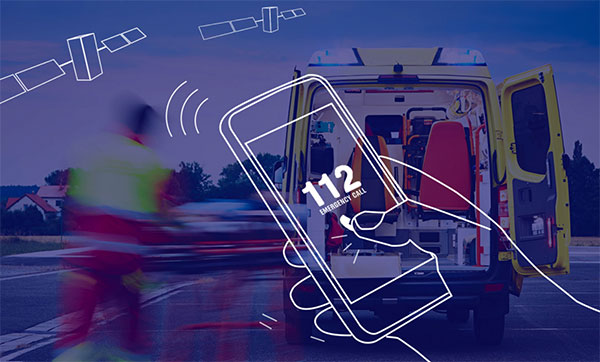
Galileo-supported E112 will result in faster response times and more lives saved. (Image: EUSPA)

Galileo-supported E112 will result in faster response times and more lives saved. (Image: EUSPA)

As of March 17, all smartphones sold in the European Union must be leveraging Galileo signals in addition to other GNSS for calls to the European 112 (E112) emergency number.

Using Galileo enhances pinpointing locations of 112 calls in Europe, resulting in faster response times and more lives saved, according to the EU Agency for the Space Programme (EUSPA).

The 112 emergency number is operational in nearly all EU Member States, as well as other countries. People in danger can call it 24/7 to reach the fire brigade, medical assistance and the police.

Most calls to the 112 emergency number are placed from mobile phones. These calls already support the sending of location information to emergency services. However, this information was not based on GNSS capabilities until recently.

Three years ago, the Commission Delegated Regulation anticipated measures to take advantage of GNSS and Wi-Fi location capabilities in smartphones placed on the European Union market, starting March 17.

GNSS versus cell-ID

Until now, the 112 caller’s location information was established through identification technology based on the coverage area of a cellular network tower (cell-ID). The average accuracy of this information varies from two to 10 kilometers, which can lead to significant search errors following emergency calls.

By contrast, GNSS location information pinpoints the call within a few meters. This level of accuracy will have a major impact in terms of response times, ultimately allowing for quicker intervention in emergency situations.

Galileo 112 rollout

The ability for 112 to communicate a caller’s location to emergency services automatically is already being rolled out. The protocol — Advanced Mobile Location (AML) — is being deployed across the European Union. When a caller dials 112 from their smartphone, AML uses the phone’s integrated functionalities and data from Galileo to accurately pinpoint the caller’s location and transmit it to a dedicated endpoint, usually a Public Safety Answering Point (PSAP), which makes the caller location available to emergency responders in real time.

According to the European Emergency Number Association (EENA), at least 18 EU Member States have already completed AML deployment, while others are in the process of doing so. This implementation is because of EU initiatives and projects such as the Help 112 project, which was set up to evaluate the merits of handset-based technologies in improving the location of emergency callers.

Publicerad den Lämna en kommentar

Hexagon | Veripos expands SPAN GNSS+INS portfolio for dynamic positioning

Ensures safe operations through reliable, robust and continuous positioning with GNSS+INS integration

Hexagon | Veripos has expanded its inertial solution SPAN GNSS+INS technology from NovAtel, also part of Hexagon, to dynamic positioning (DP) applications and vessels.

SPAN technology delivers a deeply coupled GNSS and inertial navigation system (INS) that provides robust, reliable and continuous centimeter-level positioning for operators to maintain safety and maximize uptime.

With a GNSS+INS solution, DP vessels can bridge outages in GNSS tracking and through short periods of radio-frequency interference, jamming or spoofing.

Veripos is a leader in offshore high-precision positioning, delivering reliable and trustworthy GNSS solutions such as the LD900 receiver, PPP correction services and positioning visualization software. This expertise is demonstrated through SPAN technology’s deep coupling of GNSS and inertial measurements.

Deep coupling describes how inertial measurements enhance the signal tracking for GNSS solutions, leading to improved resiliency against GNSS outages and enabling rapid reacquisition in case of interruptions. SPAN technology builds system robustness against potential signal outages, interference or disruptions while optimizing operational efficiency.

“The robust positioning, heading, velocity and attitude measurements generated from a deeply coupled GNSS and inertial solution like SPAN technology is a game-changer to dynamic positioning operations,” said David Russell, marine segment portfolio manager at Hexagon’s Autonomy & Positioning division. “SPAN technology has a proven track record of bridging outages, enabling rapid reacquisition of signals, and building a reliable and robust positioning system. It’s the best option for vessels to ensure an added layer of resiliency and achieve continuous centimeter-level accuracy across all conditions.”

SPAN GNSS+INS technology is compatible with commercial inertial measurement units (IMUs) and scalable with the LD900 GNSS receiver, Quantum visualization software and APEX correction services.

Image: Hexagon

Image: Hexagon

Publicerad den Lämna en kommentar

Surveyors: Always in the ‘middle’ of something…

Image: U.S. Census Bureau

Image: U.S. Census Bureau

The surveying profession is intrinsically involved with many functions of today’s communities and environment. When we take a closer look at the roles we play, the surveyor is usually found in the middle. Here are a few examples.

  • For new developments and infrastructure, surveying takes place after a client decides to begin a project. Site data must be collected, drafted and presented to the client, engineers and architects for design.
  • Upon completion of the engineering design, the surveyor provides layout services for the construction company to build the structure.
  • Once the improvements are completed, the surveyor provides surveys as well as record drawings for confirmation of construction to satisfy government agencies and financial backers.
  • In a property dispute, the surveyor becomes the center of attention — our professional opinion determines the correct location of the subject boundary.

This responsibility also extends to the geospatial sectors within the surveying profession. Data collection is a critical step to creating and maintaining efficient geographic information system (GIS) databases that correctly depict existing infrastructure and parcel boundary layers. With the surveyor at the center of many of these duties and tasks, no wonder that we sometimes feel we have a bullseye on our backs.


Knowing how to compute the center is an important aspect of the surveyor’s duty.


However, the word center takes on a different connotation when it comes to data and objects. Properly identifying the center of specific sets of data or objects is important when working with construction information and geospatial data. Properly measuring and marking the center of an installation has its challenges, so knowing how to compute the center is an important aspect of the surveyor’s duty.

Why is the center of an object important?

Every object that is definable in a two-dimensional space has a physical center. Whether the object is a regular or irregular polygon in plane geometry, there are various methods for determining its center.

Figure: Tim Burch

Figure: Tim Burch

These figures are easy to understand and simple to solve. More complex figures require more calculations, including coordinate geometry.

Figure: Tim Burch

Figure: Tim Burch

These examples of regular and irregular polygons have something in common: all are based upon two-dimension space, which is flat in nature. But what happens if we need to determine the center of a shape that does not fall on a 2D surface? What if the data being reviewed for a center resides on a spherical surface and contains diverging axes?

As surveyors, we break our work down to smaller coordinate systems to work around the fact our data resides on a spherical surface, but some datasets require the information to remain as latitude and longitude. One dataset is population counts, otherwise known as the census.

The U.S. Census and the ‘center of population’

The U.S. Census Bureau has been at work since early colonial times. This excerpt from the bureau website explains its purpose and foundation.

The U.S. Constitution requires only that the decennial census be a population count. Since the first census in 1790, however, the need for useful information about the United States’ population and economy became increasingly evident.

The decennial census steadily expanded throughout the nineteenth century. By the turn of the century, the demographic, agricultural, and economic segments of the decennial census collected information on hundreds of topics. The work of processing these data kept the temporary Census Office open for almost all the decades following the 1880 and 1890 censuses.

Recognizing the growing complexity of the decennial census, Congress enacted legislation creating a permanent Census Office within the Department of the Interior on March 6, 1902. On July 1, 1902, the U.S. Census Bureau officially “opened its doors” under the leadership of William Rush Merriam.

Counting the citizens of the United States was one thing, but mapping them was another. Once the final count was completed and mapped, the information was used to determine a unique location: the center of population. Here is more from the Census Bureau on the calculation basis:

The concept of the center of population as used by the U.S. Census Bureau is that of a balance point. The center of population is the point at which an imaginary, weightless, rigid, and flat (no elevation effects) surface representation of the 50 states (or 48 conterminous states for calculations made prior to 1960) and the District of Columbia would balance if weights of identical size were placed on it so that each weight represented the location of one person.

More specifically, this calculation is called the mean center of population.

This sounds like an easy exercise for a room of mathematicians and mappers, right? On the contrary, my fellow geospatialists!

How do they determine the center of population?

Computing the center of population for the United States would be much easier if we existed on a two-dimensional plane, as previously discussed. Since we don’t, however, it requires a much more difficult method of calculation to get us closer to a real-world solution:

To avoid unduly complex factors in the computations, the mathematical formulae used were those that would be precise for a true sphere. On such a sphere, the north-south distances between parallels of latitude are identical and distances in degrees may be used as units of distance. On the other hand, distances between meridians on longitude lines, are not constant but decrease from the equator toward the poles. However, if the length of one degree along the equator is used as the unit of measurement, then the length in degrees of an east-west line at any other latitude can be adjusted to the measurement standard by multiplying by the cosine of the latitude.

The center of population computed by the Census Bureau is the point whose latitude (𝜙) and longitude (λ) satisfy the equations:

population equation

where 𝜙𝑖, 𝜆𝑖 and 𝑤𝑖 are the latitude, longitude and population attached to the basic small units of area used in the computation.

Stated in less mathematical form, the latitude of the center of population was determined by multiplying the population of each unit of area by the latitude of its population center, then adding all these products and dividing this total by the total population of the United States. The result is the latitude of the population center.

East-west distances were measured, or computed, in substantially the same manner, but with the inclusion of a correction for latitude. For these distances, a degree of longitude at the equator was the unit of measurement. East-west distances along the equator could be measured in degrees, but any east-west degree distance north of the equator — where all the United States is located — had to be adjusted to recognize the convergence of meridians toward the poles. This adjustment required that each east-west distance, stated in degrees of longitude, be multiplied by the cosine of the latitude. This mathematical relationship is precise for a sphere and a very close approximation for the earth.

The computation required that the longitude of each of the thousands of selected points be multiplied by the cosine of the latitude of the point and by the population associated with the point. These products were added and divided by the sum of the products for the same thousands of points, each of which was obtained by multiplying the cosine of the latitude of a point by the appropriate population figure. The result was the longitude of the center of population.

(Courtesy of the Geography Division, U.S. Census Bureau, published November 2021)

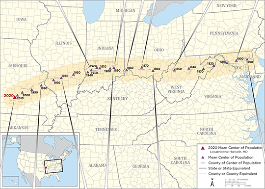
Here is a graphic from the U.S. Census identifying significant historical events along with the westward movement of the center of population:

Image: U.S. Census Bureau

Image: U.S. Census Bureau

Here are the locations with corresponding latitude/longitude for the centers from 1790 to 2020:

Mean Center of Population of the United States, 1790–2020
Census year North latitude West longitude Approximate location
United States
2020 37.415725 92.346525 Wright County, MO, 14.6 miles northeast of Hartville.
2010 37.517534 92.173096 Texas County, MO, 2.7 miles northeast of Plato.
2000 37.69699 91.80957 Phelps County, MO, 2.8 miles east of Edgar Springs.
1990 37.87222 91.21528 Crawford County, MO, 9.7 miles southeast of Steelville.
1980 38.13694 90.57389 Jefferson County, MO, 1/4 mile west of DeSoto.
1970 38.46306 89.70611 St. Clair County, IL, 5 miles east-southeast of Mascoutah.
1960 38.59944 89.20972 Clinton County, IL, 6-1/2 miles northwest of Centralia.
1950 38.80417 88.36889 Clay County, IL, 3 miles northeast of Louisville.
Conterminous United States
1950 38.83917 88.15917 Richland County, IL, 8 miles north-northwest of Olney.
1940 38.94833 87.37639 Sullivan County, IN, 2 miles southeast by east of Carlisle.
1930 39.06250 87.13500 Greene County, IN, 3 miles northeast of Linton.
1920 39.17250 86.72083 Owen County, IN, 8 miles south-southeast of Spencer.
1910 39.17000 86.53889 Monroe County, IN, in the city of Bloomington.
1900 39.16000 85.81500 Bartholomew County, IN, 6 miles southeast of Columbus.
1890 39.19889 85.54806 Decatur County, IN, 20 miles east of Columbus.
1880 39.06889 84.66111 Boone County, KY, 8 miles west by south of Cincinnati, OH.
1870 39.20000 83.59500 Highland County, OH, 48 miles east by north of Cincinnati.
1860 39.00667 82.81333 Pike County, OH, 20 miles south by east of Chillicothe.
1850 38.98333 81.31667 Wirt County, WV, 23 miles southeast of Parkersburg.
1840 39.03333 80.30000 Upshur County, WV, 16 miles south of Clarksburg. Upshur County was formed from parts of Barbour, Lewis, and Randolph Counties in 1851.
1830 38.96500 79.28167 Grant County, WV, 19 miles west-southwest of Morefield. Grant County was formed from part of Hardy County in 1866.
1820 39.09500 78.55000 Hardy County, WV, 16 miles east of Moorefield.
1810 39.19167 77.62000 Loudoun County, VA, 40 miles northwest by west of Washington, DC.
1800 39.26833 76.94167 Howard County, MD, 18 miles west of Baltimore. Howard County was formed from part of Anne Arundel County in 1851.
1790 39.27500 76.18667 Kent County, MD, 23 miles east of Baltimore.

Data: U.S. Census Bureau

Not to be confused with the geographic center…

The geographic center of area is the point at which the surface of the United States would balance if it were a plane of uniform weight per unit of area. That point, approximately 44.967° north latitude and 103.767° west longitude, is located west of Castle Rock in Butte County, South Dakota, as it has been since Alaska and Hawaii became states.

The geographic center of the conterminous United States (48 states and the District of Columbia) is located near Lebanon in Smith County, Kansas, at approximately 39.833º north latitude and 98.583º west longitude.

The center of population as geospatial data

The plotting of the center of population makes for an interesting study of westward expansion in early U.S. history. Once the contiguous 48 states were founded, plotting the center shifts to regional changes . The truly interesting part of these calculations and plotting for the past several centuries falls into an area of expertise called geospatial data.

While some liberties were taken early on using large, populated areas as one data point, we now can count literally every person and their geospatial location. However, it needs to be recognized that early efforts to count our population and track its center every 10 years meets the criteria for being called geospatial data. They just didn’t yet know what that meant.

Speaking of surveyors…

Here are several events and initiatives happening this month, an important month for surveyors.

logo-natl surveyors week

2022 National Surveyors Week

National Surveyors Week was established by the National Society of Professional Surveyors as an annual event to bring public recognition to the surveying profession and the vital services surveyors provide to the advancement and betterment of human welfare.

During this week, thousands of professional surveyors throughout the country will take part in local activities designed to introduce a new generation to the profession and highlight the use of technology in their day-to-day work.

Activities for National Survey Week (or anytime!)

  1. Have a Survey Day at your local mall.
  2. Sponsor a Trig-Star Test: www.trig-star.com.
  3. Conduct a Scouts Merit Badge event.
  4. Obtain a proclamation from your state or local government.
  5. Organize geocaching or benchmark hunting: Geocaching.com.
  6. Try surveying mark recon: SurveyMarkHunting.pdf.
  7. Help with the National Geodetic Survey’s GPS on Benchmarks Campaign: GPS on BMs

For more ideas on how to get involved, visit National Surveyors Week 2022.

Photo:

2022 Global Surveyors’ Day

Global Surveyors’ Day 2022 will be held Monday, March 21. This annual event is a way to globally recognize groundbreakers, pioneers, individuals and the industry that has shaped our history and continues to be of great value to our communities.

2022 Global Surveyor of the Year
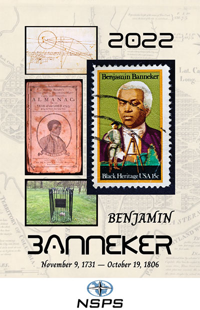
Image: NSPS

Image: NSPS

As part of the Global Survey Day and National Surveyors Week, every year on March 21 a professional surveying association is tasked with choosing a Global Surveyor of the Year. For 2022, the National Society of Professional Surveyors has been selected to choose a person with a historical surveying background for this prestigious honor. After thorough consideration, NSPS has chosen Benjamin Banneker (1731–1806) for 2022 Global Surveyor of the Year.

The selection was brought before the NSPS Board of Directors during our Spring 2021 meeting and passed by a majority vote. While Banneker’s career as a surveyor was limited in time and experience, his additional contributions to math, science, astronomy and publication of a groundbreaking almanac have earned him a significant place in American history.

We also selected Banneker because of his ability to overcome the adversity of being a free Black man in early colonial America. Through much self-teaching, he was able to excel at the contributions previously listed in a period when Blacks were not accepted for their educational abilities.

The selection committee chose Banneker over the three presidents who are famously chiseled on Mount Rushmore and Henry David Thoreau, an author who also surveyed to fund his writing career. The committee felt that Banneker’s contributions not just to the surveying profession made him deserving of this honor, but considered his total body of work created when Black men were not generally accepted as capable human beings. Our world needs more people like Benjamin Banneker and would be a better place because of them.

No time like the present to promote our geospatial professions

Surveying and geospatial careers are more important than ever, so examples like the center of population help depict applications that us these skills. Please consider promoting our wonderful professions during these events and throughout the year. The profession you promote may provide an opportunity to bring new faces and ideas to our ranks very soon.

Publicerad den Lämna en kommentar

Swift Navigation and Taoglas partner on precision GNSS solutions

Partnership to bring integrated precision GNSS solutions to automotive and industrial customers

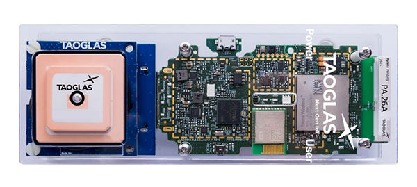
Swift Navigation, a San Francisco-based GNSS firm, and Taoglas, a provider of internet of things (IoT) solutions, have announced a strategic partnership to integrate their technologies to deliver pre-tested, low-risk, high-precision GNSS solutions to a broad customer base.

The Taoglas EDGE RTK Starter Kit has high-precision GNSS with U.S. 4G/3G cellular connectivity. (Photo: Taoglas)

The Taoglas EDGE RTK Starter Kit has high-precision GNSS with U.S. 4G/3G cellular connectivity. (Photo: Taoglas)

The partnership will provide positioning solutions for automotive, micromobility, delivery, robotic and industrial customers. Specifically, the Taoglas EDGE Locate IoT platform and EDGE RTK Starter Kit now come pre-integrated with Swift’s Skylark precise positioning service.

Bringing pre-integrated, high-accuracy positioning products to these industries in an easy-to-implement solution will greatly improve the accuracy of the positioning data delivered, the companies state.

Together, Swift and Taoglas deliver high-precision GNSS solutions to customers around the globe by utilizing Taoglas’ IoT platforms and Swift’s Skylark seamless, cloud-based corrections — available in advanced SSR (state space representation) or industry-standard formats. The pre-integration allows customers to bypass module-level validation, integration and engineering efforts with an out-of-the-box solution.

“Swift Navigation is excited to begin this partnership with Taoglas and align our visions of making accurate positioning easily accessible across industries,” said Swift CEO Timothy Harris. “We look forward to offering our products as an integrated solution to make it easier for customers across the globe to benefit from affordable and accurate positioning.”

“We are delighted to be partnering with Swift Navigation to enable companies to overcome the challenges of delivering their high-precision positioning-based IoT solutions.,” said Ronan Quinlan, co-founder and joint CEO of Taoglas. “Our worldwide team of design, development, test and manufacturing engineers is dedicated to delivering IoT software and hardware solutions on time, the first time, for leading technology enterprises.”

Additional products will soon be available from Swift, Taoglas and their channel partners. Customers have the ability to pre-order now by contacting sales@swiftnav.com or oemiotsales@taoglas.com.