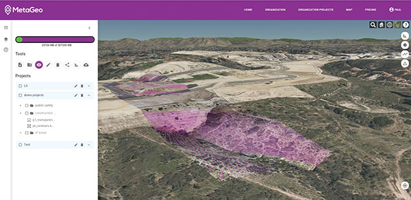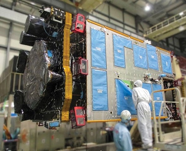
QZS-R1 is prepped for testing. At left is the Earth-oriented surface that hosts the L-band antenna. (Photo: JAXA)
By Peter Steigenberger, Steffen Thoelert, Sergei Yudanov and Markus Ramatschi
The Japanese QZS-1R satellite was launched on Oct. 26, 2021, from the Tanegashima Space Center in Japan. It serves as a replenishment for QZS-1, the first spacecraft of the Japanese Quasi-Zenith Satellite System (QZSS) in orbit since September 2010.
QZS-1R joins the current QZSS constellation of three satellites in inclined geosynchronous orbit (IGSO) and one geostationary satellite. These four Block I satellites transmit the L1C/A signal at 1575.42 MHz.
QZS-1R, as well as future QZSS satellites, are able to transmit the new L1C/B signal. L1C/B is based on the same family of gold codes as L1C/A, but uses a binary offset carrier (BOC) modulation instead of the binary phase-shift keying (BPSK) and a different PRN range (203–206).
Compared to BPSK, the BOC modulation adds a square wave subcarrier with a frequency of fsc = 1.023 MHz that equals the chipping rate of the ranging code. This subcarrier shifts the peak spectral energy from the center frequency fL1 to fL1 ± fsc to reduce interference with the GPS L1C/A signals.
During in-orbit testing (IOT) from late November until early December 2021, QZS-1R transmitted L1C/A and L1C/B signals intermittently. FIGURE 1 shows a spectrum of the L1-band transmissions of QZS-1R recorded on Nov. 25 with the 30-meter dish antenna of the German Space Operations Center in Weilheim, Germany, as well as a spectrum of QZS-2 recorded in July 2017.

Figure 1. L1 spectra of QZS-1R (red) transmitting L1C/B and L1C, as well as QZS-2 (blue) transmitting L1C/A and L1C. The spectra were measured with DLR’s 30-meter high-gain antenna on Nov. 25, 2021, and July 20, 2017, respectively. (Credit: DLR)
During IOT, QZS-1R had an extremely low maximum elevation of 0.8° in Weilheim. Due to technical restrictions for such low elevations, QZS-1R had to be observed with a sidelobe of the 30-meter antenna. As a result, the respective observations are much more noisy than the QZS-2 reference data.
Nevertheless, the different spectral characteristics of L1C/B and L1C/A can be clearly seen in FIGURE 1: L1C/B has two maxima at 1574.4 and 1576.5 MHz due to the BOC modulation, whereas the BPSK L1C/A signal has one maximum at the center frequency of 1575.42 MHz.
GNSS receivers of the International GNSS Service (IGS) started to track L1C/A, L1C, L2C and L5 signals of QZS-1R on Nov. 17. Aside from the regular PRN code J04, test signals using the non-standard code PRN J06 were intermittently transmitted by QZS-1R during the IOT and tracked by these receivers.
Based on the public specification of the new L1C/B signal, Javad GNSS developed a prototype firmware that enabled tracking of this signal during the early transmissions. This firmware was installed on a Javad TRE-3 receiver operated by GFZ German Research Centre for Geosciences at its IGS station WUH200CHN in Wuhan, China.
FIGURE 2 illustrates the noise and multipath characteristics of different QZS-1R pseudorange measurements. It is based on the so-called multipath linear combination of L1 pseudorange and L1/L2 carrier-phase observations covering a six-hour data arc. RMS values were computed for 5-degree elevation bins for each pseudorange signal. While the individual signals were tracked on different days of the IOT and the associated results have to be interpreted with care, the data indicate a very similar ranging performance of the legacy C/A signal and the new C/B signal. Best results are obtained with the L1C signal, which uses both a higher signal power and an advanced modulation with superior multipath suppression.

Figure 2. Noise and multipath characteristics of QZS-1R signals on the L1 frequency tracked by the IGS station WUH200CHN in Wuhan, China. (Credit: DLR)
QZS-1R will resume continuous transmission of L1C/A as soon as declared healthy. The transition from L1C/A to L1C/B is planned for 2023-2024, when an operational QZSS constellation of seven satellites is reached. The launches of the IGSO satellite QZS-5, the geostationary QZS-6, and the quasi-geostationary QZS-7 are all planned for 2023.
Also see Directions 2022: Now 3 years old, QZSS hits its stride.
Manufacturers
GNSS data used in this article were collected with a Javad GNSS TRE-3 receiver. The spectral overviews were captured with a Rohde & Schwarz FSQ26 signal analyzer.
Peter Steigenberger is a senior scientist at the German Space Operations Center of the German Aerospace Center (DLR), where he conducts research in the field of new satellite navigation systems.
Steffen Thoelert is an electrical engineer at DLR’s Institute of Communications and Navigation. His research activities focus on signal-quality monitoring and satellite payload characterization.
Sergei Yudanov is a senior firmware developer at Javad GNSS, Moscow. His main field of activity is GNSS signal processing.
Markus Ramatschi is a senior scientist at the Helmholtz Centre Potsdam, GFZ German Research Centre for Geoscience. He is operating a global GNSS reference station network.
Further Reading
Cabinet Office, Quasi-Zenith Satellite System Interface Specification: Satellite Positioning, Navigation and Timing Service, IS-QZSS-PNT-004, Jan. 25, 2021.
Ramatschi M., Bradke M., Nischan T., Männel B. (2019): “GNSS data of the global GFZ tracking network,” vol 1. GFZ Data Services. https://doi.org/10.5880/GFZ.1.1.2020.001
Thoelert S., Hauschild A., Steigenberger P., Montenbruck O., Langley R. (2017), “QZS-2 signal analysis, QZS-3 launched.” GPS World 28(9): 10–14,
Gilla detta:
Gilla Laddar in …