By Christopher Black
An accuracy test of the Locata Network — a non-GPS-based positioning system installed at the U.S. Air Force White Sands Missile Range in New Mexico — focused on timing down to the nanosecond, with impressive results.
In 2018, the 746th Test Squadron (746 TS) tested its Non-GPS-Based Positioning System (NGBPS) at White Sands Missile Range as an alternative to GNSS for precise time transfer and synchronization. This was the first independently measured and characterized testing program for the NGBPS, which leverages Locata’s radio-based position, navigation and timing (PNT) technology to achieve high accuracy independent of GPS.
Using specific parameters and equipment configurations, independent experts proved Locata’s absolute and relative time synchronization and frequency stability performance. Under testing, the NGBPS provided exceptional time transfer and frequency stability across large areas.
With these successful results in hand, the U.S. Department of Defense will be able to leverage this capability for programs requiring high-precision time and frequency distribution, without relying on GPS alone. Plus, the system is flexible — Locata’s area of transmission can be increased to cover substantially larger areas than at White Sands for safety-of-life, military or government-mandated systems.
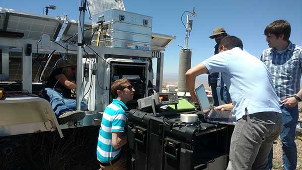
With USNO personnel, members of the 746 TS reconfigure the Master LocataLite site for the test. (Photo: 746 TS/USAF)
Background
Over the past two decades, the free availability of GPS time has enabled a plethora of time-dependent applications. Time and frequency synchronization between remote locations is crucial for digital communication systems, electrical power grids and financial networks, to name a few. Military operations also require accurate and reliable time information. Typically, these applications require accurate time synchronization ranging from 10 microseconds (μs) down to 100 nanoseconds (ns). Yet, while our critical reliance on GPS for time transfer continues to escalate, GPS remains susceptible to interference, disruption or denial.

A technician with the 746 TS re-aims a LocataLite antenna for an alternative TimeLoc configuration. (Photo: 746 TS/USAF)
Locata. Locata Corp., a privately owned Australian company with a U.S. subsidiary, invented a radio-location technology that provides precise PNT for environments where GPS coverage is unavailable. Locata ground-based PNT technology delivers positioning that, in many scenarios, far exceeds the performance and reliability of GPS. LocataNets, the company’s terrestrial networks, function as local ground-based replicas of traditional GPS position and timing services. They can be designed to reliably deliver a powerful, controllable, tailored signal as user applications require.
A LocataNet consists of synchronized LocataLite transceivers, all-in-one units that transmit and receive out of the same 10 x 5 x 1-inch box. Cables are connected to antennas for signal reception and transmission. Locata Rovers are mobile receivers within the network that use these synchronized LocataLite signals to calculate an accurate PNT solution.
The 746 TS employs the basic LocataNet laydown — multiple Slave LocataLites receive signals from a single Master LocataLite transceiver. The patented process by which slaves are synchronized to the master (or other slaves) is known as TimeLoc.
Until these new tests were run, the squadron’s attention had primarily been focused on the high-accuracy use of Locata’s position and navigation solution as an alternative to GPS when it is jammed, deceived or unreliable. But because all LocataLites are precisely synchronized via TimeLoc, network synchronization is a natural extension of Locata technology’s core capabilities.
In October 2015, GPS World reported that the United States Naval Observatory (USNO) showed LocataLites are a viable option for a stable 1 pulse per second (1 pps) distribution setup within an urban environment, where it can support applications such as cell-tower synchronization in GPS-challenged environments. The USNO tests demonstrated synchronization of less than 200 picoseconds — significantly better than any other known wireless network synchronization methodology, including GPS. If clear line-of-sight is available between a master and Slave LocataLite, precision is 50 picoseconds with frequency stability to 1×10-15 —better than a Stratum One atomic clock.
Because of the USNO’s timing expertise and familiarity with Locata TimeLoc testing, the 746 TS tasked the USNO to conduct independent synchronization experiments at White Sands, with the following objectives:
- Evaluate the Locata master, slaves and non-Locata timing receiver at the master site in reference to USNO master atomic clock time.
- Determine the Locata network’s internal, independent synchronization stability and accuracy.
- Determine the Locata Rover’s 1 pulse per second (PPS) time stability and accuracy, for use in time transfer applications.
The primary purpose of the tests was to show that nanosecond-level time transfer is possible over significantly wide areas by using Locata, and that TimeLoc technology offers a relatively easy means of supporting exceptionally high-precision time and frequency distribution over large broadcast areas.
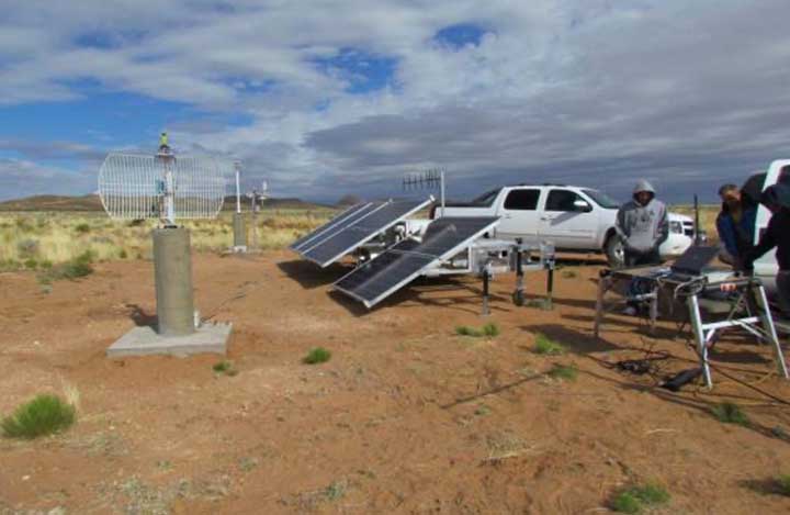
Slave LocataLite site layout. (Photo: 746 TS/USAF)
Synchronization Method
Since Locata technology was originally developed as an RF-based high-precision non-GPS-based positioning and navigation system, the time synchronization accuracy requirements for a LocataLite transceiver are very high. If centimeter positioning precision is desired for a Locata receiver, every small fraction of a second is significant; for instance, a 1-ns error in time equates to an error of approximately 30 centimeters (because of the speed of light).
TimeLoc is a patented high-accuracy wireless synchronization method developed by Locata Corp. It allows LocataLites to achieve high levels of synchronization without atomic clocks, external control cables, differential corrections or a master reference receiver.
The TimeLoc procedure is described in the following steps for synchronizing two LocataLites (see Figure 1).
- LocataLite A transmits a unique signal (code and carrier).
- The receiver section of LocataLite B acquires, tracks and measures the signal generated by LocataLite A.
- LocataLite B generates its own unique signal (code and carrier) which is transmitted, but, importantly, it is also received by the receiver section of LocataLite B.
- LocataLite B calculates the difference between the signal received from LocataLite A and its own locally generated and received unique signal. Ignoring propagation errors, the differences between the two signals are due to the clock difference between the two devices and the geometric separation between them.
- LocataLite B adjusts its local oscillator to bring the differences between its own signal and LocataLite A to zero. The signal differences are continually monitored and adjusted so that they remain zero. In other words, the local oscillator of B follows precisely that of A.
- The final stage is to correct for the geometrical offset (range) between LocataLite A and B, using the known coordinates of the LocataLites. When this step is accomplished, TimeLoc has been achieved.
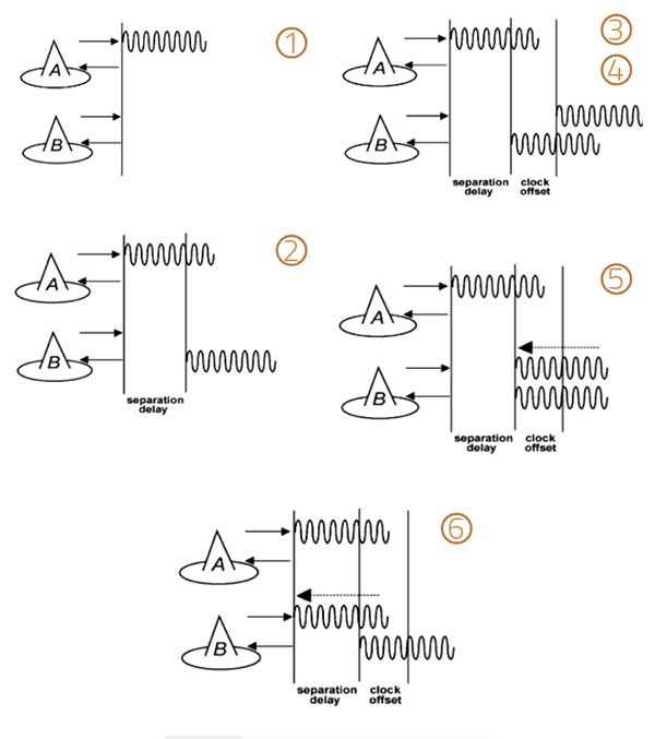
Figure 1. The TimeLoc process. (Image: Author)
The only requirement for establishing a LocataNet using TimeLoc is that LocataLites must receive signals from one other LocataLite. However, received signals do not have to come from the same central or Master LocataLite, because this may not be possible in difficult environments or when propagating the LocataNet over large areas. Instead, a LocataNet can “cascade” TimeLoc through intermediate LocataLites. For example, if a third LocataLite C can only receive the signals from B and not Master LocataLite A, it can use B’s signals for time synchronization instead of A’s, provided that B has already TimeLoc’d to the network. Therefore, by using “cascaded TimeLoc,” there is theoretically no limit to the number of LocataLites that can be synchronized.
Test item description
The NGBPS at White Sands consists of an operational LocataNet, where each node (a site instrumented with a LocataLite) is synchronized via Locata’s patented TimeLoc technique. The LocataNet, combined with a mobile Rover, is a subsystem of the 746 TS Ultra-High-Accuracy Reference System (UHARS), which provides PNT information in GPS-denied environments. The NGBPS operates in the 2.4-GHz industrial, scientific and medical band, which is far enough away from GPS frequencies to be unaffected by GPS jamming. Although it is currently used as a source of position truth during GPS jamming, the 746 TS understands that the NGBPS is potentially a source of high-accuracy timing data as well.
The UHARS is in the northern portion of White Sands Missile Range. It typically consists of 16 LocataLite sites. The master site is at North Oscura Peak, or NOP (labeled Northridge in Figure 2); all other sites are time synchronized to that master site.
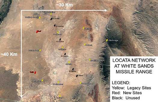
Figure 2. Locata network at White Sands Missile Range. (Image: Author)
Each LocataLite site consists of:
- one LocaLite
- two monuments—pillars for antenna placement (Note: The two new sites lack the permanent monuments for antenna placement)
- two transmit antennas
- one receive antenna
- one meteorological station—for meteorological data
- one communication antenna
- one trailer for power and transport
The communications antenna at each site is attached to a UHF modem that is used for 746 TS remote control of the LocataNet. This allows remote data logging, reconfiguration or monitoring of the network without having to drive to each site. However, it should be noted that no communications system whatsoever is required for the Locata NGBPS TimeLoc capability to run.
To support the timing tests, the LocataNet was reconfigured several times to meet requirements of specific test objectives. These configurations are described below.
Static ground tests
Static ground tests involved multiple configurations. The first (Figure 3) consisted of two LocataLites (master and terminal slave) collocated at NOP close enough that their respective PPS outputs could be compared in a single time interval counter. A terminal Slave LocataLite was installed at NOP specifically for this test.
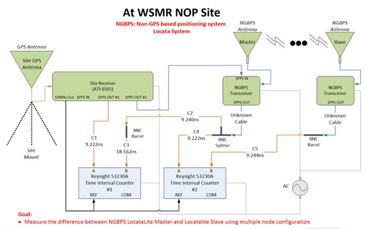
Figure 3. LocataLite Configuration 1: North Oscura Peak (NOP) site test instrumentation. (Image: Author)
This setup also facilitated simple network reconfiguration to change the number of LocataLite sites being tested. By programming LocataLites to TimeLoc to specific sites at White Sands and redirecting their respective antennas accordingly, the TimeLoc chain under test could be expanded to have multiple sites between the LocataLite master and the collocated terminal slave without changing measuring equipment instrumentation at NOP. This means that the time transfer could hop, or cascade, between one or more sites and be measured with the same test instrumentation.
Configuration 2 consisted of three LocataLites: The master at NOP, a slave at Gran-Jean and the terminal slave at NOP. Again, the master and terminal slave were collocated close enough to each other that their respective PPS outputs could be compared in a single time interval counter, but this time the network was configured to cascade the TimeLoc signal through the slave at Gran-Jean, 29.20 km away. Since the TimeLoc signal now had to cascade through two sites and travel from the master at NOP to Gran-Jean and back to the terminal slave at NOP, the effective TimeLoc travel distance was 58.40 km (Figure 4).
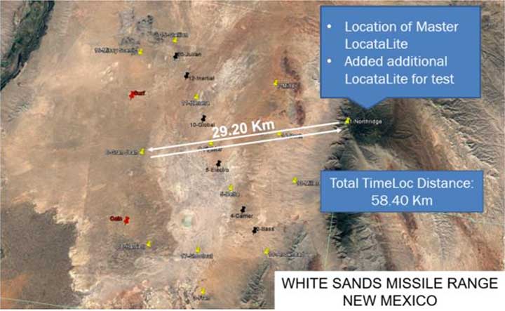
Figure 4. LocataLite Configuration 2: Total TimeLoc distance is 58.40 km. (Image: Author)
Configuration 3 consisted of four LocataLites: The master at NOP, a slave at Gran-Jean, a slave at Missy-Scenic and the terminal slave at NOP. This configuration forced the TimeLoc signal to cascade through three sites and travel a total distance of 73.84 km (Figure 5).

Figure 5. LocataLite Configuration 3: Total TimeLoc distance is 73.84 km. (Image: Author)
Ground vehicle test
For Configuration 4, a Locata Rover was instrumented on the squadron’s Small Test Vehicle (STV), which drove all accessible roads within the LocataNet’s coverage (Figure 6). During this mobile test, the LocataNet was configured with 10 active LocataLites. The Locata Rover in the vehicle used Locata signals from available nodes to calculate Locata network time, which was synchronized to the GPS timing receiver at NOP. The data collected determined how well network time is synchronized while in a moving vehicle.
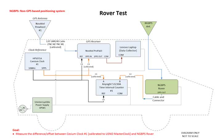
Figure 6. Rover test installation on Small Test Vehicle. (Image: Author)
Test results
To collect the required data, USNO first had to characterize the performance of the master site’s GPS timing receiver at NOP, and then synchronize it to two separate USNO atomic clocks that could be used as remote timing references for the tests. The GPS timing receiver is equipped with a rubidium oscillator, which produces a GPS-disciplined 1 pps output signal. Its internal rubidium clock is a stable source of time with an advertised UTC (USNO) offset of a best case 15-ns root mean square (RMS) and a worst case 100-ns RMS.
The cesium clocks output 5- or 10-MHz sinusoids and a 1 pps signal. The cesium clocks output 5- or 10-MHz sinusoids and a 1 pps signal and were characterized relative to the USNO correction receiver, which USNO personnel had characterized relative to UTC. Correction data available from a time interval counter could then be applied to tie the timing receiver back to USNO time. The measurements at NOP recorded the difference between the timing receiver and the cesium clocks. Using the relationship between the cesium clocks and UTC (USNO), one could characterize the timing receiver’s time relative to USNO time.
The USNO calibrated measurements at the nanosecond level using two methodologies. The most common approach was simply to compare two 1 pps signals, a method known as “tick-tick.” Another important methodology is referred to as a “tick-phase,” which is a measurement of a sinusoidal signal compared to a 1 pps reference. Some timing equipment will have discrete time jumps with certain tick-phase measurements, because of how narrow the distance between the rising edges of a sine wave is compared to a 1 pps signal.
There’s a chance that the 1 pps signal is close to two rising edges of a sine wave, causing the signal to jump back and forth in its timing measurement, depending on which rising edge of the sine wave it uses.
Measurements were further complicated by the delicate nature of cesium clocks, which perform best under finely controlled laboratory conditions. Each cesium reference exhibits its own characteristics that must be observed, measured, and accounted for. Moreover, transporting them to White Sands Missile Range for this test where temperature fluctuations, moving vehicle vibrations, and altitude variations among devices were introduced made synchronization of these clocks particularly challenging. For example, USNO discovered that the Cesium Clock #1 had its internal batteries disconnected — possibly through the original shipment to White Sands, the constant vehicle vibrations while driving on the range, a faulty wiring in the battery terminals, or possibly a combination of all. This problem induced a random offset in the clock, and calibration had to be re-accomplished to reestablish traceability back to UTC (USNO).
Figure 7 shows each cesium clock’s measured drift rate in nanoseconds/second and its corresponding linear fit. This trendline can then be used to project cesium clock #2 to the past and compare it to the measurements of cesium clock #1.
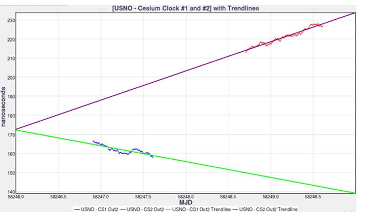
Figure 7. USNO cesium clocks with trendlines. (Image: Author)
Figure 8 shows the relationship between the timing receiver and USNO master clock and its linear fit. Performing linear fit approximations of the cesium clocks likely introduced unknown errors, potentially increasing the variance of the 1 pps differences.
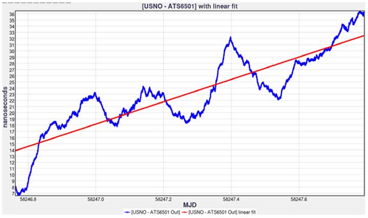
Figure 8. USNO versus timing receiver with linear fit. (Image: Author)
Comparing the 1 pps outputs of the LocataLite master and collocated LocataLite slave to the master site reference clocks (CS2 or timing receiver 1 pps out), the data is traceable back to USNO using the linear fits found for both the USNO timing receiver and cesium clock #2 (Figure 9).
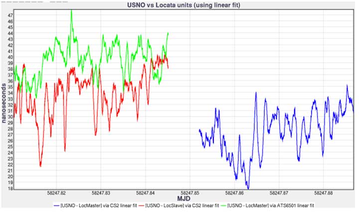
Figure 9. USNO compared to Locata system for May 9, 2018, time interval counter measurements. (Image: Author)
LocataLite timing measurement bias was within 40 ns, and the stability was within 3.7 ns of the reference clocks (see Table 1). The stability of the system is encouraging, as the mean offset can be driven down by more precise measurements and more precise calibrations such as using a two-way satellite time-transfer calibration method (TWSTT).
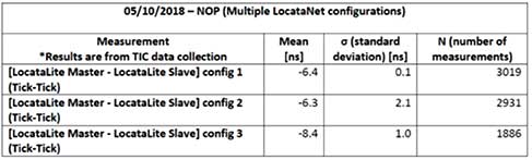
Table 1. USNO compared to Locata system tabulated values and statistics. (Image: Author)
In Table 2, we compare measured data of the 1 pps outputs of the LocataLite master to the collocated LocataLite slave and compute the Locata network internal synchronization in each of the network configurations tested. The data reveals that the network synchronization accuracy is ≤ 2.1 ns. Unfortunately, during Configuration 2 testing, which propagated the TimeLoc signal from NOP to Gran-Jean and back (a total distance of 58.40 km), a technician inadvertently obstructed line-of-site between Locata antennas and consequently temporarily disturbed TimeLoc. Those data points were not removed before this analysis, which is why the reported standard deviation in that configuration, although quite good at 2.1 ns, is nevertheless uncharacteristically high.
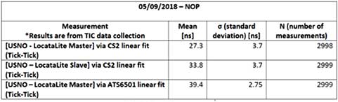
Table 2. LocataNet internal synchronization. (Image: Author)
Finally, Figure 10 shows the timing measurements between the USNO master clock and the mobile Locata Rover, via the cesium clock #1 linear fit. Unlike in the LocataLite tests, the Rover is not TimeLoc’d to the network. Instead, it simply calculates its time from LocataLite signals within its line of sight, similar to how a GPS device will calculate its time from satellite signals. During this test, the Rover’s calculated timing accuracy showed a mean of 5.4 ns and stability within 9.7 ns of the USNO master clock, while driving all over the northern portion of the range. To produce the plot, 927 outliers were removed (3 sigma). The outliers occurred at the beginning and ending of the test, when the vehicle was moving from its parking location at Stallion Range Center (outside the operational LocataNet) to the test route and back. The buildings in the area obstructed line of sight and induced significant multipath, which degraded the Rover’s calculations.
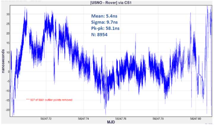
Figure 10. USNO LocataLite Rover via CS1 linear fit. (Image: Author)
Conclusion
This endeavor for USNO to characterize the 746 TS NGBPS was met with many challenges, which emphasize the real-world difficulty of measuring time at these extremely fine levels in the field using atomic clocks. The USNO found that some non-linearity started occurring in the USNO – Cesium Clock #2 measurements because of the container of Cesium Clock #2 not being ideal for temperature stability. They also discovered that Cesium Clock #1 had its internal batteries disconnected due to an unknown cause. However, because of deliberate measurements between Cesium Clock #1 and Cesium Clock #2, the USNO was still able to provide calibration measurements but with degradation in the measurement clarity.
From the data collected, USNO personnel found:
- The GPS timing receiver at NOP produced 1 pps timing accuracy consistent with its 15-ns RMS specification. Therefore, the reference time delivered to the Master LocataLite was synchronized to UTC within 15 ns.
- A standard deviation measurement from Master LocataLite to UTC of under 4 ns.
- Locata’s master-to-slave internal time synchronization (independent of GPS) was measured to be between 100 ps and 2.1 ns in 3 different Locata network configurations spanning distances up to 73.84 km (45.88 miles).
- The timing measurements in the mobile Rover test show its ability to provide accurate time with a standard deviation of around 10 ns.
Many lessons learned throughout this experiment could be implemented to get more accurate measurements, especially when looking at the accuracies of the GPS time transfer throughout the NGBPS. Looking ahead, more accurate calibration values for both the GPS timing receiver and the Master LocataLite could be made by using a TWSTT method. This would simplify the number of measurements and provide a 1 pps signal of USNO’s master clock, resulting in up to 1 ns of accuracy in the reference time delivered to the Master LocataLite. Depending on the requirements of customers needing NGBPS time at White Sands, the 746 TS and USNO can potentially recharacterize the NGBPS timing accuracy and stability using this methodology.
Manufacturers
The LocataLites and Rovers that create much of the 746 TS NGBPS are manufactured by Locata Corp. The NGBPS synchronized to GPS time via a Microsemi ATS6501 timing receiver. The cesium clocks were Hewlett-Packard 5071A cesium primary frequency standard devices. The USNO used a Novatel ProPak3 for correction data, measured using a Keysight 53230A time interval counter.
Christopher Black earned a B.S. and M.S. in electrical and computer engineering from New Mexico State University. In November 2017 he joined the 746th Test Squadron, Holloman Air Force Base, as a navigation warfare analyst. Now, as lead reference engineer, he heads up research, development and maintenance of the squadron’s reference systems, including UHARS.
This article has been approved by the USAF for public release, #AEDC2019-205.
Gilla detta:
Gilla Laddar in …