In this second installment of our review of innovations in GNSS receivers, we present the responses from ComNav Technology, Raytheon, TeleOrbit and Unicore to the same questions that we posed to CHC Navigation, Eos Positioning Systems, Hemisphere GNSS, Hexagon | Novatel, Javad GNSS, Septentrio and Trimble in the January issue:
- utilizing Galileo and BeiDou
- dealing with jamming and spoofing
- integration with inertial measurement units (IMUs) and other sensors
- positioning using cell phones and other consumer devices
- any other areas or challenges they find particularly significant.
All four respondents in this issue, like to those in the January issue, report that they are making full use of the new GNSS signals available, taking hardware and software measures to counter jamming and spoofing, and integrating IMUs and other sensors with their GNSS receivers to help achieve continuous navigation and positioning in obstructed environments. In addition, they are continuing to develop mass-market applications, because high-precision positioning is becoming increasingly important for cellphones and wearable devices. For a fuller review of these trends, see my introduction to the first installment.
Notably, two of the companies featured in this issue, ComNav Technology and Unicore, are Chinese.

Raytheon
With Chad Pillsbury, Senior Director, Raytheon Intelligence & Space’s Resilient Navigation and Reconnaissance Solutions
Utilizing Galileo and BeiDou
Integration and fusion of multiple space position services is a key element in achieving assured positioning, navigation and timing (PNT). A combination of commercial and military-code navigation signals, when coupled with evolving sensors, provide more resilient methods of navigation and enable new concepts of operations related to PNT. Over the next two years, RI&S will customize these concepts of operation (CONOPS) for our United States and international allies to harness the power of fusion in resilience.
Dealing with jamming and spoofing
As threats to GPS continue to evolve and mature, RI&S continues to develop alternative navigation solutions, as well as GPS-capable receivers and antennas, aimed at defending against a variety of spoofing and jamming technologies. Our latest anti-jam, anti-spoof and high-precision solutions leverage a recent technology breakthrough that lowers size, weight, power and cost while boosting performance in the new M-code and alternative navigation applications.
Integration with IMUs and other sensors
IMUs are the cornerstone of high-performance navigation systems and will continue to be in the future. Recent innovations allow some systems to become more IMU agnostic, or even to consider microelectromechanical systems (MEMS) IMUs depending on performance, which can allow the customer greater flexibility and a more open architecture.
Positioning with consumer devices
RI&S sees 5G as a game-changing technology, with a lot of possibilities in the assured navigation market. We also look to cellphones as a great area of interest — especially for exploring unforeseen signals, considering human international models, and learning how the next generation of GPS users expect to see PNT information displayed.
Other significant challenges and opportunities
The future of GPS lies in a system-of-systems approach. Using time as a backbone, navigation systems can securely share time, data, position and intent across the network. Broadly, this approach can be used in civil, commercial and military environments. RI&S is fully focused on developing capabilities to achieve this ideal state.

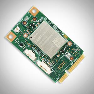
Unicore Communications
With Gao Jingbo, Marketing Director
Utilizing Galileo and BeiDou
Most of Unicore’s high-precision products support all constellations and multiple frequencies. The new BeiDou 3 provides precise point positioning (PPP) service from three geostationary satellites via the B2b frequency, while Galileo offers up to five frequencies — E1, E5a, E5b, E5 AltBOC and E6. End users will benefit from improved PNT availability, reliability and continuity as access to those signals greatly reduces multipath effects and allows faster PPP convergence times.
Dealing with jamming and spoofing
To effectively deal with signal jamming and spoofing, it is important to know their sources. GNSS receivers also are susceptible to electronic interference and vulnerable to complex electromagnetic environments. Unicore integrates GNSS RF, baseband and algorithms into a single GNSS system-on-chip (SoC) that mitigates external interference. Joint time-frequency domain interference mitigation technology also is adopted in chip design.
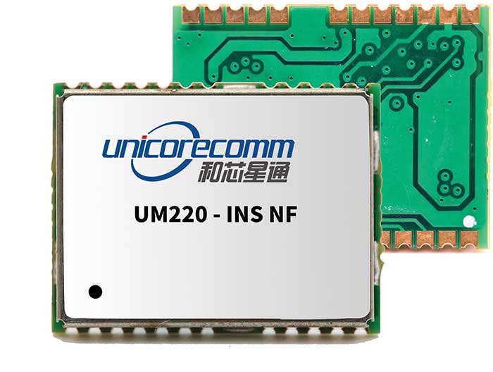
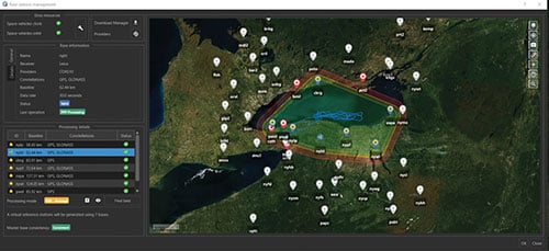
Photo: Unicore Communications
Integration with IMUs and other sensors
Demand for seamless, accurate indoor-outdoor location is increasing. The integration of GNSS with IMUs, lidar, cameras and other sensors helps achieve continuous navigation and positioning in obstructed environments such as urban canyons and tunnels. Unicore offers receivers integrated with both high-end IMUs and affordable MEMS-based devices. Dual-frequency GNSS plus MEMS provides an ideal positioning solution for automotive applications.
Positioning with consumer devices
High-precision positioning is becoming increasingly important for cellphones and wearable devices, and multi-scenario adaptation is necessary. Instead of integrating standalone GNSS chips with smartphone processors, cellphone manufacturers prefer to cooperate with GNSS manufacturers through GNSS intellectual property (IP) licensing. To ensure high-precision service, better cellphone antennas are also important.
Other significant challenges and opportunities
We strive to deliver reliable, timely and smart positioning for anything, anywhere, anytime. Next-generation GNSS location products and services should be more end-user-friendly. The hardware interface will be more universal, flexible, configurable and adaptable with different algorithms for a diverse range of applications.

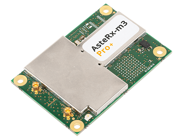
Teleorbit
With Daniel Seybold, CEO
Utilizing Galileo and BeiDou
Our GOOSE receiver has been able to use Galileo since its beginning and BeiDou since the forth quarter of 2020. Signals from both can be used individually or with other signals (GPS, Galileo, GLONASS and BeiDou, plus SBAS).
Dealing with jamming and spoofing
Open Service Navigation Message Authentication (OSNMA) is now implemented on the GOOSE, which helps mitigate spoofing attacks. GOOSE’s recording function enables users to record simulated jamming/spoofing attacks, and then analyze the behavior of the GOOSE and the received signals. We are developing various GNSS antenna arrays for nulling and beamforming, as well as a left- and right-hand circular polarized (LHCP/RHCP) antenna with GOOSE adaption for signal processing.
Signal conditioning on the GOOSE platform is based on a high-rate discrete Fourier transform (DFT)-based data manipulator algorithm, known as an HDDM algorithm, that fulfills multiple roles. The HDDM algorithm removes a wide range of interference signals, equalizes the spectrum, or restructures the spectrum.
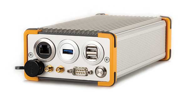
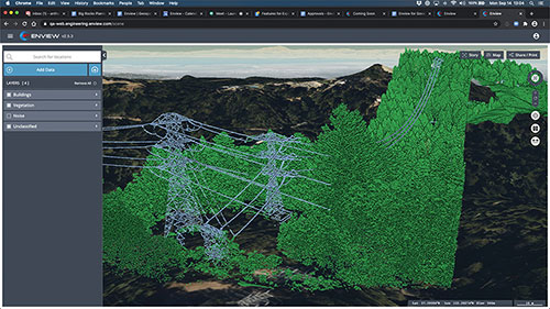
Image: Teleorbit
Integration with IMUs and other sensors
We offer a GNSS antenna with an integrated IMU. Thanks to its open software interface, fusing IMU or other sensor data with GNSS data is easily done with GOOSE. Vector tracking, deep coupling and other sensor fusions (for example, 5G) are on the GOOSE roadmap.
Positioning with consumer devices
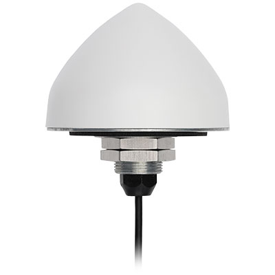
Our ongoing AMELIE project will study advanced techniques for the miniaturization and radiation enhancement of GNSS mass-market antennas to be applied in the design, manufacturing and testing of a multi-frequency, low-cost, high-gain dual circularly polarized antenna for the next generation of consumer devices. In 2021, we will build the following antenna demonstrators: single-frequency (L1/E1), dual-frequency (L1/G1/E1, L5/E5a/E5b) and multi-frequency (L1/G1/E1, L5/E5a/E5b, L2, E6).
Other significant challenges and opportunities
GOOSE can track the Galileo E5AltBOC (wideband) signal, which provides code-range variances below a few decimeters. This offers a significant increase in the accuracy of code measurements in terms of reduced noise and mitigation of multipath effects, compared to conventional signals. GOOSE will provide two different approaches for robust tracking: vector tracking for dealing with challenging environments where multipath occurs or buildings block signals, and adaptive tracking to allow the receiver to acclimate to its surroundings by adapting the bandwidth in the loop depending on movement, such as high dynamics.
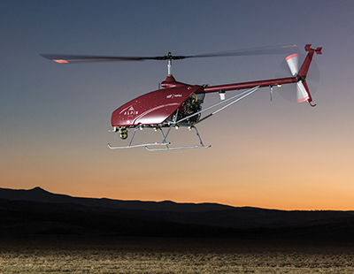
ComNav Technology
With Min Xu, Director of GNSS Technology R&D Department
Utilizing Galileo and BeiDou
We keep up with the development of GNSS. Our new K8 series of high-precision GNSS modules support the recently completed BDS-3 and Galileo constellations concurrently, significantly improving positioning accuracy especially when signals are partially obstructed. Despite their complex design, the size of K8 modules decreased by almost 36% from their precursors and power consumption dropped to 1.0W, making them easier to integrate.
Dealing with jamming and spoofing
We have developed algorithms to eliminate specific forms of jamming and spoofing, with a focus on narrowband interference. The newly released Quantum III SoC chip — integrated with wideband signal-receiving technology, wideband and narrowband anti-interference technology, and anti-continuous wave interference technology — can provide high-quality observation information in a complex electromagnetic environment.
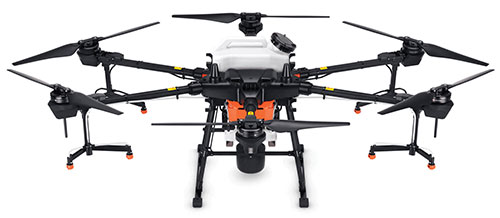
Photo: ComNav Technology
Integration with IMUs and other sensors
There is an increasing need to add IMUs to supplement obstructed GNSS signals. Empowered by a high-precision IMU, our N5 receiver supports tilt survey with accuracy of less than 2.5 cm. Users can survey without a centering bubble as its calibration-free tilt compensation protects it from magnetic disturbances. We are also focusing on image sensors, such as cameras and radars, to make data collection more flexible and reliable.
Positioning with consumer devices
Our high-precision products are mainly used in professional fields such as land surveying, deformation monitoring, and UAVs. We are continuing to explore GNSS products for consumer markets, which are sensitive to power consumption and cost. The upcoming M10 GNSS is a compact and portable receiver for mass-market applications, such as person or vehicle tracking and fleet management.
Other significant challenges and opportunities
GNSS technology can be widely applied in agriculture, transportation and infrastructure construction. We developed the AG360/AG360 Pro Agricultural Automatic Driving system, which drives autonomously without damaging crops. We collaborated with China Mobile to build more than 2,000 CORS stations to provide high-precision positioning services in support of smart-city construction, IoT and location-based services.