The Ingenuity UAV is still buzzing around on Mars, well past its anticipated evaluation/test lifetime, and is still providing intriguing video and photographic coverage of the surface. Having established that it can fly in the Martian atmosphere and having achieved all its own test objectives, its role is now that of a “pathfinder” — in the truest form of the word — scouting out routes for its big brother Perseverance rover.
The principle objective of the mission remains the search for signs of life, and this is now being performed by the SUV-sized land-bound ground unmanned vehicle (GUV) rover. The project is managed by NASA/Jet Propulsion Laboratory (JPL).
Since our earlier stories covered the phenomenal achievements of the little 2 Kg UAV, it’s reasonable that we provide details of its development and design, largely by JPL and AeroVironment.
Talking with the Ben Pipenberg, the AeroVironment engineering lead for the Ingenuity program, it was clear that the company’s role had been to bring its extensive unmanned experience to the requirements for flight on the red planet. It turns out flying high-altitude pseudo-satellite unmanned aircraft at up to 90,000 feet teaches you a lot about vehicle dynamics in very thin air, and AeroVironment has been doing that for many years. The company developed Ingenuity’s rotor and rotor-drive systems, and the minimal weight structure of the vehicle.
JPL developed the flight-control systems, power system, telecoms and electronics that enabled communications, navigation, guidance, video and control of Ingenuity on Mars.
Mars is cold, especially at night, reaching as low as –148 °F. It has few clouds, is long way from the sun, and has a very thin atmosphere. When JPL decided to use mostly off-the-shelf components, the added task of keeping the electronics warm using minimal power became absolutely essential. Power is provided by a lithium-ion battery pack with its own heaters and temperature control, which is recharged by a small solar photo-electric panel mounted on the top of the vehicle above the rotors.
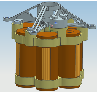
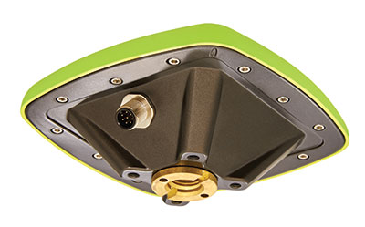
Integrity’s lithium-ion battery, heaters and temperature sensors. (Diagram: Aerovironment)

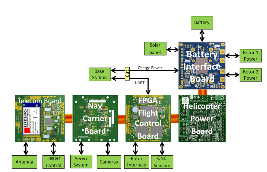
The avionics and interface boards. (Diagram: Aerovironment)
The electronics are carried in the electronics core module (ECM), which is mounted inside the insulated box and mechanically attached to a central, hollow, structural tube, on which the flight motors, rotors and landing legs are all attached. The electronics box has a 3-cm gap between the skin and the ECM, which is filled with inert, insulating carbon dioxide gas — heat retention and power management are the basics for survival on the Mars surface. Keeping the batteries above –15 °C is the design goal for the temperature control system, which also enables the electronics and sensors to survive and operate.
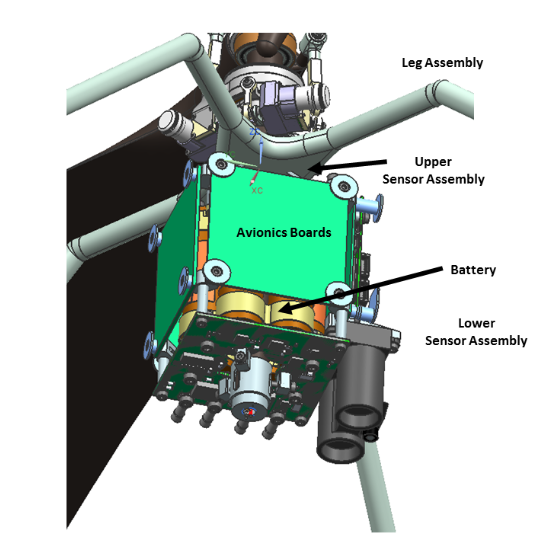
The ECM assembly. (Diagram: Aerovironment)
Principle vehicle elements. (Diagram: Aerovironment)
The avionics boards are wrapped around the heated battery-pack with the battery interface board at the bottom, along with the FPGA/flight controller board (FFB), the NAV/servo controller board (NSB), the telecom board (TCB) and the helicopter power board (HPB) mounted vertically. The navigation camera (NC) and the return-to-Earth (RTE) camera are both slung from the front, lower (direction of flight) side of the ECM, peering through a clear window in the insulated box.
The FPGA basically runs the show, managing most tasks, especially two redundant flight controller microprocessors. An additional CPU controls power through several interfaces to the vehicle systems, including the motors driving the rotors. The CPU also runs control software that initiates mode changes based on external commands, and guidance/navigation — using data from the inertial measurement unit (IMU), the nav camera and altimeter — limiting position, velocity and attitude drift. The telecom module manages communications and some power functions, and the power board manages vehicle power.
Off-the-shelf sensors are interfaced to the FPGA and include the nav camera, two dual redundant three-axis micro-electro-mechanical (MEMS) IMUs, an inclinometer for IMU calibration on the surface, and an altimeter. These sensor outputs are used to produce a velocity solution, derived helicopter position and attitude. The nav camera provides images compared frame by frame to stored topography to derive an estimate of vehicle velocity while airborne.
The FPGA is responsible for flight and attitude control, waypoint guidance, maintenance of system time, running a motor-control loop and fault management, as well as providing power management and some thermal control. The FPGA also manages multiple redundant interfaces between the various subsystems, and telemetry communications back to the rover during flight. It also operates the two redundant flight control processors, determining when to switch from one to the other, and provides stored critical data to each processor whenever power is cycled.
As anyone involved in space electronics knows, one of the main design constraints for Integrity was to minimize the effects of single-event upsets (SEUs). SEUs are largely due to cosmic ray effects on electronic components that are not specifically hardened against them. This means most of the electronics used on this particular unmanned vehicle may be susceptible to SEU failures, even though MIL-SPEC, extended-temperature-range components were used wherever possible. Nevertheless, there are dual-redundant IMUs, so one is kept on standby, and the key FPGA is MIL-SPEC, radiation tolerant and has three parallel, duplicated channels. Other components were pre-selected for tolerance to latch-up; a current monitor helps detect such latch-ups with power cycling used to clear these events.
Meanwhile, on Mars Integrity completed its 13th flight on Sept. 4, taking photos toward the southwest of the South Seítah region of Jezero Crater, and flying slower and lower than in previous expeditions. The object was to gather more detail of raised ridges and outcrops from a different angle than the 12th flight — an area in which the science team may have particular interest. It’s possible that the Perseverance rover may soon find itself exploring this area.

Integrity photographs the South Séítah region during its 12th flight. (Photo: NASA/JPL)

Integrity takes a shadow “selfie” during its13th flight. (Photo: NASA/JPL)
As unremarkable as this scene might appear to us laymen, there is a ridgeline in the middle of the left shot where the team may soon decide to send Perseverance to dig, drill and scoop.
Tony Murfin
GNSSAerospace
Acknowledgements
Aerovironment: Ben Pipenberg, the company’s extensive role in the Ingenuity project is summarized in a presentation for the recent AUVSI Xponential convention in Atlanta.
NASA/JPL: Integrity’s development is described in depth in NASA/JLP paper “Mars Helicopter Technology Demonstrator,” which is a principle source of material for this article.
Gilla detta:
Gilla Laddar in …